FAÇADE SYSTEMS
THE VERTICAL VARIANT.
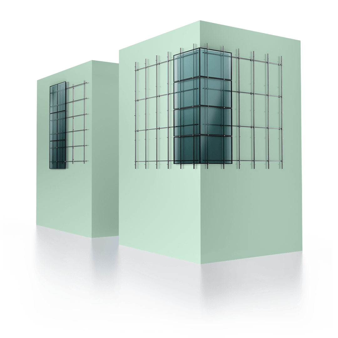
Schletter’s vertical solar mounting systems integrate seamlessly with your building façade – combining efficient solar energy use with quality, durability, and aesthetics. Choose from elevated or parallel systems designed specifically for façades.

Schletter’s solar mounting systems for façades are designed for a quick and hassle-free assembly process. With user-friendly design principles, installation becomes straightforward, saving you valuable time and effort.
Our mounting systems include optimized stationary sections, enabling precise adjustments to achieve the desired panel inclination. You have complete control over the angle, ensuring optimal energy generation for your solar panels.
Fine-tune the positioning of your solar panels effortlessly. Schletter’s solar mounting systems allow you to adjust in 5-degree increments, providing flexibility and customization options tailored to your requirements. This single-row module assembly accommodates a range of 50-75° inclinations with facade supports.
Our systems are engineered to withstand the test of time, providing you with a reliable and enduring solar solution that meets the highest standards of excellence, even in challenging environmental conditions. Our commitment shines through in every detail of our systems to ensure long lasting stability.
SAFETY INFORMATION
RELEVANT REGULATIONS FOR MOUNTING PV TO FAÇADES.
When mounting photovoltaic plants to building façades, specific regulations must be observed as defined by the glass manufacturers. As well as the usual warranty risks such as roof leakage or damage to modules, there is an additional risk of injury to people in the event of substandard fastening or through the selection of inappropriate modules.
The following recommendations should help the planner/installer to mitigate such risks and to ensure a secure and professional design:
- All standards and approval conditions pertaining to construction must be observed when implementing solar projects for façades.
- The designated PV installer is obligated, as expert in the field, to inform the end customers of all potential risks and of required approvals, and must observe the valid standards as "State of the Art".
- As a matter of course, each module assembly mounted to a building façade should be treated as an individual case, particularly where the deployment surface is a public building and where the area beneath the façade assembly is generally accessible.
There are two fundamental variations:
- The term vertical glazing is used if the photovoltaic module is mounted parallel to the wall, either directly on or with a specific clearance to the surface.
- Overhead glazing is the term used if modules are mounted a certain angle, resembling a form of "canopy structure" where the area beneath the modules is publicly accessible.
In both cases, irrespective of whether damage is caused by negligence (tension in glass, incorrect mounting, thermal tension, etc.) or whether a module is damaged through external influences, there is a fundamental risk of glass shards falling from the assembly and causing injury to passers-by.
- Vertical or overhead glazing is only approved in publicly accessible areas if the possibility of injury due to falling glass fragments can be ruled out in the event of damage to a laminate glass part (including a PV module).
- Vertical or overhead glazing is deployed using appropriate composite glass materials (generally VSG and ESG materials): The modules are protected against shattering by a laminated film which can hold glass together for a period of time after breakage.
- Overhead laminate glass systems may have a generic type of approval which offers authorization for deployment in specific areas.
- In addition to the materials deployed, the fastening method and the module arrangement generally have a great influence on utilization in the vertical or overhead positions.
- As a general principle, photovoltaic modules are not approved for mounting in an overhead assembly. This applies to both framed and unframed modules. PV modules are also designed, technically, in glass-film compound format, but are nevertheless not approved for deployment as an overhead laminate assembly. More information on this subject can be obtained from the respective manufacturer.
- In the event that PV modules are proposed as a façade or overhead solution, a specific method of fastening is generally imposed (e.g. a linear arrangement of laminated modules).
- It is possible for a system with a non-approved design for application in overhead assemblies to be approved, as an "exceptional case" for deployment in certain projects. Approval for exceptional deployment generally requires a positive destructive test on several components (in the case of PV modules this may be more expensive than for glass components). Several test specimens are damaged and the laminate film must prove capable of holding fragments together over a specific period, guaranteeing that no dangerous shards can break free and cause injury.
- DIN EN 410, Glas im Bauwesen - Bestimmung der lichttechnischen und strahlungsphysikalischen Kenngrößen von Verglasungen (Glass in building - Determination of luminous and solar characteristics of glazing); Version: 1998-12
- DIN 1249-10, Flachglas im Bauwesen; Chemische und physikalische Eigenschaften (Flat glass in building; chemical and physical properties); Version: 1990-08
- DIN 1249-11, Flachglas im Bauwesen; Glaskanten; Begriff, Kantenformen und Ausführung; (Flat glass in building; glass edges, definition of terms, edging and execution); Version: 1986-09
- DIN 1249-12, Flachglas im Bauwesen, Einscheiben-Sicherheitsglas; (Flat glass in building, Single-layer safety glass); Version 1990-02
- DIN 1259-1, Glass - Part 1: Begriffe für Glasarten und Glasgruppen; (Terms for glass types and glass groups;) Version: 2001-09
- DIN 1259-2, Glas - Teil 2; (Glass - -Part 2): Begriffe für Glaserzeugnisse; (Terms for glass products); Version: 2001-09
- DIN EN 14449, Glas im Bauwesen; (Glass in building); Verbundglas und Verbund-Sicherheitsglas; (Laminated glass and laminated safety glass): Konformitätsbewertung/ Produktnorm, Deutsche Fassung (Conformity assessment/ Product standard, German version) EN 14449: 2005 European standard, version July 2005
- DIN 52337, Prüfverfahren für Flachglas im Bauwesen; Pendelschlagversuche (Test procedures for flat glass in building; pendulum impact test); Version: 1985-09
- DIN 52338, Test procedures for flat glass in building; ball drop test for laminated glass Version: 1985-09
- DIN 52349, Structure after fracture of glass used in buildings. Version 1977
- DIN EN ISO Laminated safety glass film properties (tear resistance and elongation at rupture)
- Draft of technical regulations for the dimensioning and design of glazing with punctiform glazing supports (Entwurf der Technischen Regeln für die Bemessung und Ausführung punktförmig gelagerter Verglasungen, eTRPV.)
- DIBt TRAV: Technische Regeln für die Verwendung von linienförmig gelagerten Verglasungen; (Technical regulations for the use of linear arranged glazing);
- GUV 56.3 Mehr Sicherheit bei Glasbruch; (More safety in the event of glass breakage);
This selection of literature should be used as fundamental reference material relating to glass construction:
- Glasfibel. (Publ..: Bundesverband des deutschen Flachglas-Großhandels, 1983)
- Wörner, J-D.; Schneider, J. (Authors): Abschlussbericht zur experimentelllen und rechnerischen Bestimmung der dynamischen Belastung von Verglasungen durch weichen Stoß; TU Darmstadt/German Institute for Building Technology; 2000
- Charlier, H.: Bauaufsichtliche Anforderungen an Glaskonstruktionen, Der Prüfingenieur Nr.11 (1997), S.44-54
- Sedlacek, G/Blank, K./Laufs, W/Güsgen, J.: Glas im konstruktiven Ingenieurbau, Bauingenieur Praxis, Ernst & Sohn, 1.Auflage, Berlin, 1999
CONTACT US
REQUEST a consultation.


